In electrical installations, numerous networks are laid out for various purposes—power circuits, circuits for measuring devices, relay protection, and automation. The primary objective when laying cables of different purposes is to ensure the proper functioning of all devices and equipment elements, which is only possible in the absence of unwanted interference and electrical inductions. In this article, we will consider the requirements for the simultaneous installation of power and low-voltage cables, as well as the primary methods for installing different types of networks.
Requirements for joint installation
When considering the joint installation of cables for different purposes, the required documentation and instructions are not always available. Equipment manufacturers provide standards regarding the correct layout of required circuits, but in this case, recommendations are given regarding the installation of circuits for a single device or equipment element. This means that it does not take into account that during the installation of a large amount of equipment or complex systems, various wiring interacts differently.
Therefore, when technical upgrading is necessary, involving the replacement of various circuits, besides the recommendations of the manufacturers, the experience of operating networks of different purposes should be considered. If, in an electrical installation, the equipment and its connecting cable wiring have functioned correctly without interference for many years, then when replacing the wiring, the previous requirements for the mutual laying of circuits of different voltages should be observed.
However, it's important to consider that if there's a change in equipment type, different devices and systems are used, or different cable types are applied, the old rules become irrelevant because a complete reconstruction of the object essentially creates a new system. In such cases, it is necessary to adhere to the requirements outlined below.
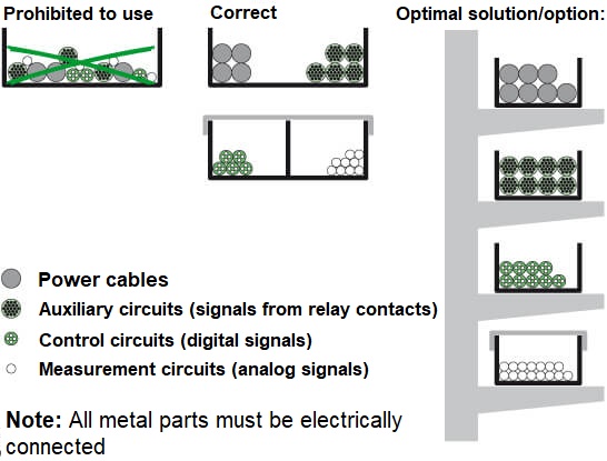
In a single conduit, wire bundle, or cable tray, it is permitted to route power and low-voltage cables of different purposes jointly: for control, protection, signaling, measurement, etc., with a voltage up to 440 V, both AC and DC, except for:
- - circuits from multiple independent power sources that provide mutual backup;
- - secondary switching circuits of relay protection and automation devices, metering instruments, which can generate mutual interference exceeding permissible values and disrupt the normal operation of these devices;
- - low-voltage wiring with a voltage of up to 42 V, laid to ensure safety against electric shock;
- fire alarm and automation circuits.
When joint routing of power and low-voltage cables is necessary using open methods, such as cable trays, channels, etc., the following recommendations should be followed:
- 1. For one-sided cable routing, it's necessary to separate power and low-voltage cables with asbestos partitions characterized by sufficient fire resistance. In this case, power cables should be placed above the low-voltage ones. If low-voltage networks provide redundancy, they should also be separated by partitions or, where possible, laid in different channels, on different shelves, etc.
- 2. Parallel routing of power cables (up to 1000 V class) and low-voltage (e.g., control) cables on different shelves or in different compartments is permissible, provided that it does not compromise safety requirements.
- 3. For two-sided cable routing, the electrical wiring should be separated: power on one side, low-voltage on the other, as shown in the diagram below.
- 4. The minimum distance between horizontal cable-containing structures should be no less than 100 mm.
If there is no possibility or it's impossible to determine the mutual influence of certain circuits, they should be routed separately. Typically, during the initial months of operating installed equipment and devices, it's possible to detect all errors, rectify them, and ultimately achieve the most optimal joint routing of networks with different purposes.
Methods of installation
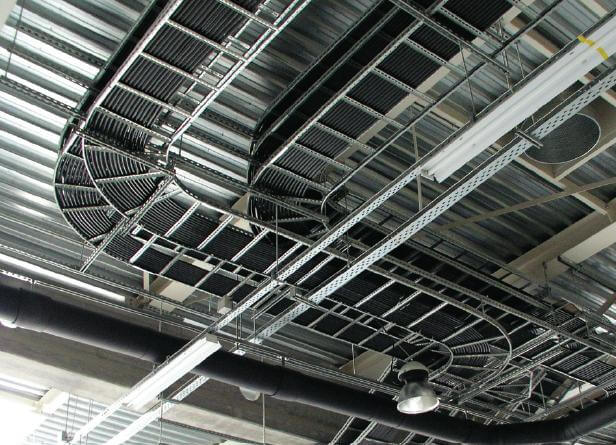
In electrical installations, cable lines are routed in various ways depending on local conditions.
Outside buildings, cable lines are typically laid in cable channels and galleries of underground and overhead types, constructed with reinforced concrete slabs or trays. To bring cable lines from the cable channel directly to the equipment element, metallic conduits or corrugated pipes with hardware ensuring sufficient protection against environmental factors are used.
Depending on the location of the electrical installation and requirements for accessibility, mechanical protection, fire safety, and other factors, cable lines may be laid in pipes, manholes, trenches in the ground, or tunnels.
Inside buildings, cables can be routed jointly in cable channels integrated into structural elements, above suspended ceilings, in metal or plastic conduits of various types, or openly along walls and other structures, if this doesn't contradict the requirements stipulated by electrical installation regulations. Depending on the relative placement of junction boxes, equipment elements, and various devices, connections between them can be established using both cables and wires within conduits.
"For the convenience of laying electrical wiring and saving space in cable management systems, trunk cables with numerous cores are used, merging circuits of different purposes, which can be routed together.
Depending on the distance between junction box assemblies, connections between them can be established using either cables or wires within conduits.
So, we've covered how power and low-voltage cables can be routed together. Hopefully, the information provided has been helpful to you!
(с) Samelectrik